About DDC
The Display Data Channel, or DDC, is a collection of protocols for digital communication between a display and a graphics adapter that enable the display to communicate its supported display modes to the adapter and that enable the computer host to adjust monitor parameters, such as brightness and contrast.
Objective
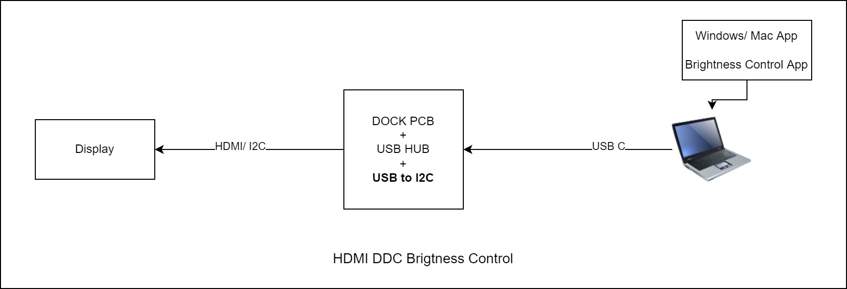
The DDC commands uses the I2C protocol for the data communication. We have designed a USB to HDMI Dock and the dock SoC used on the doesn’t support the DDC commands for brightness and contrast adjustment . To provide the display brightness and contrast adjustment functionality in dock, we wanted to design a application that will send the I2C commands directly to the display. For the interfacing, we have USB to I2C adaptor to directly send the I2C commands from the computer’s USB port to the display. There is no need of intermediate microcontroller for the communication between the display and computer.
Hardware Setup
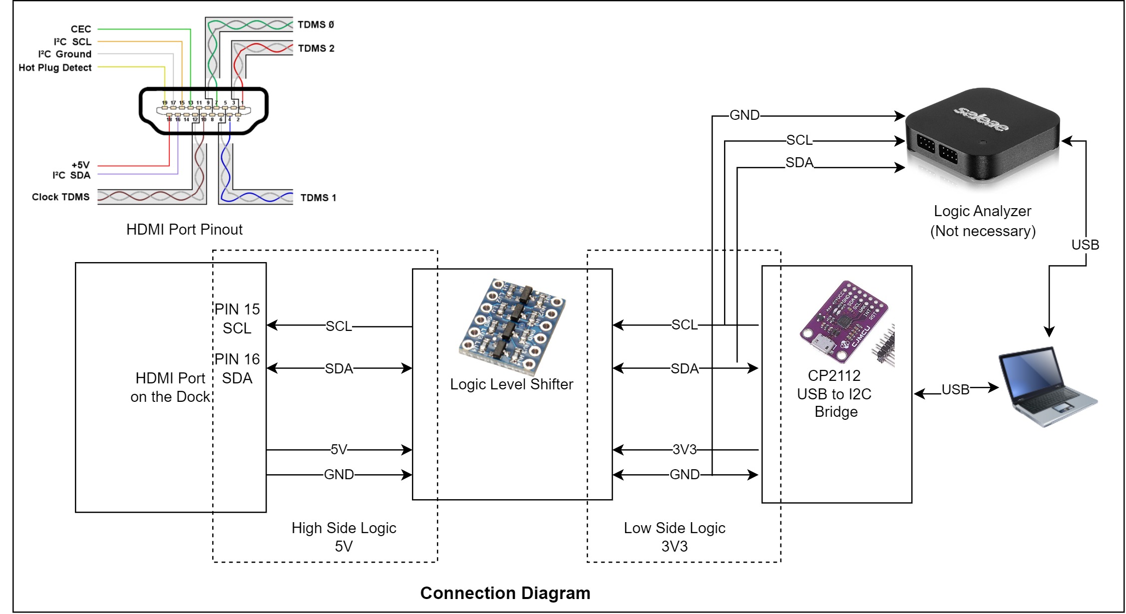
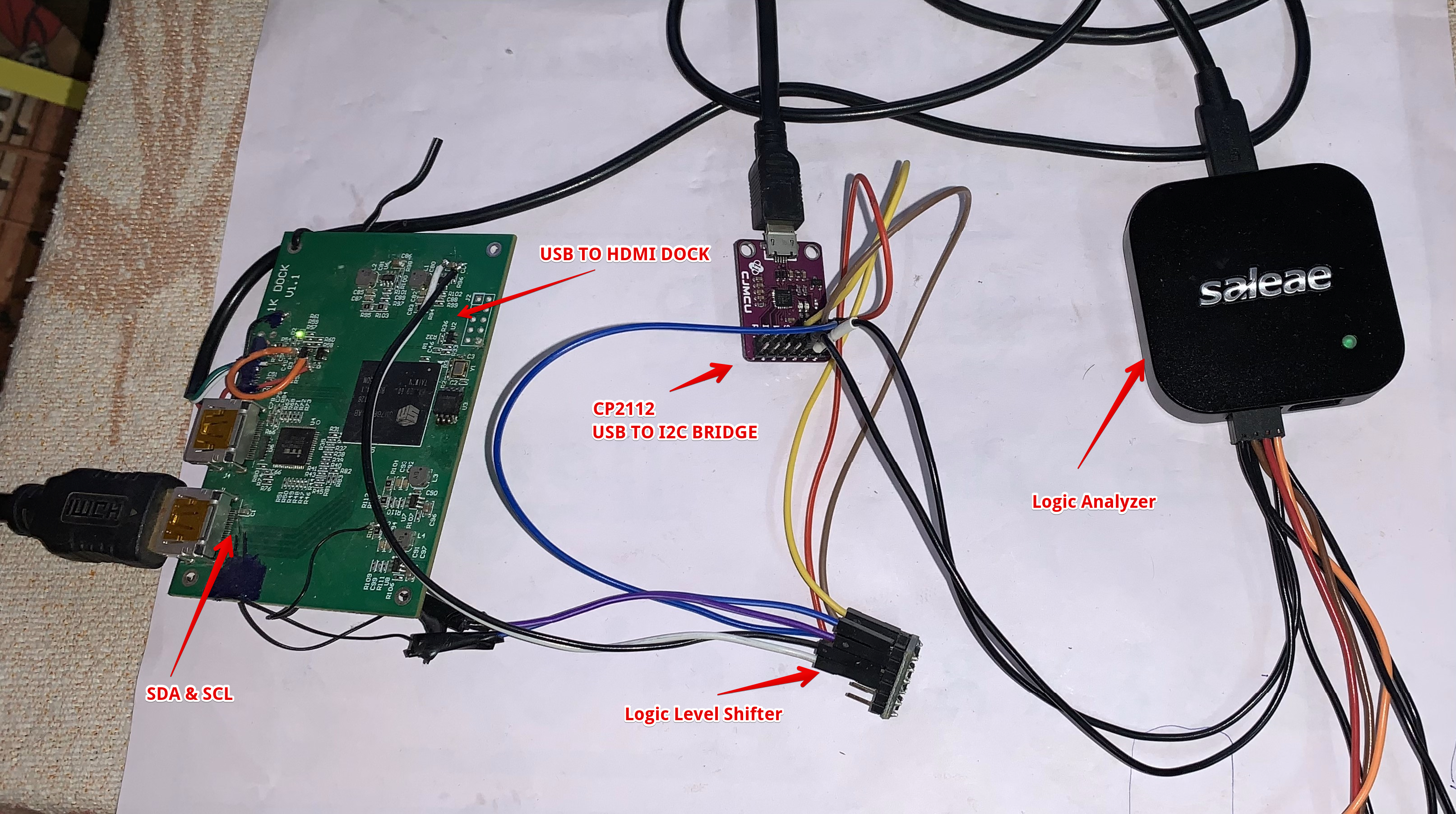
- A CP2112 USB to I2C bridge module is used for the sending the I2C commands from Windows application to HDMI display.
- Bridge module is connected to a Logic level shifter module because the bridge modules works on 3.3V logic and HDMI I2C channels works on 5V logic.
- The Bridge module SDA and SCL pins are connected to the HDMI port SDA and SCL lines.
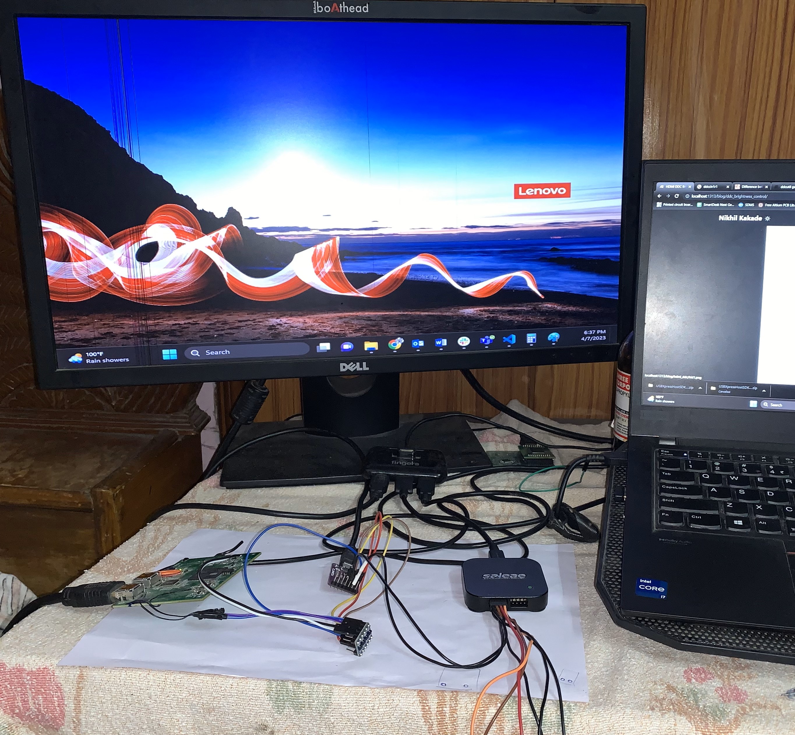
- A DDC supported HDMI display is used for testing. (Not all display supports the DDc commands).
I2C commands
VCP commands are used to set the parameters. There are two type of VCP function.
- GetVCP (To get the information from display like name, input mode, current brightness/contrast values)
- SetVCP (To set the display parameter like brightness/contrast, input type, volume). SetVCP data parameters
6E Destination address
51 Source address
84 Length
03 Set VCP Feature COMMAND
CP VCP opcode
SH High byte
SL Low byte
CS CheckSum
Brightness Control
To send the I2C command from the computer, we have used the CP2112 HidSmbus Utiltiy provided by SilconLabs. Silsiocn Labs also provided the SDK that contains all the information for the CP2112 APIs to deveiop a Windows/Mac/Linux application. For the testing we have used the demo ‘HidSmbus example’ application prvided bt Silicon Labs in the SDK.
Download the CP2112 SDK from here.
Extract and open the HidSmbus example.exe from SiliconLabs\USBXpressHostSDK\CP2112\Release\x86
After oprmimg the appication, select the connection (i.e. CP2112 module) and click on connect.
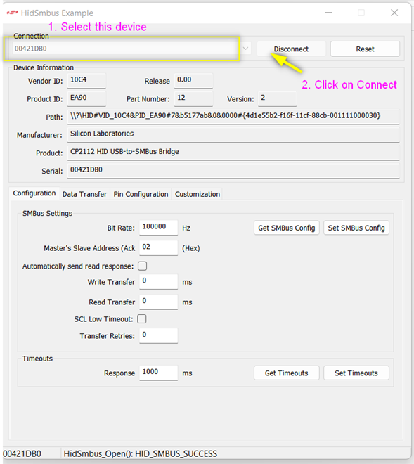
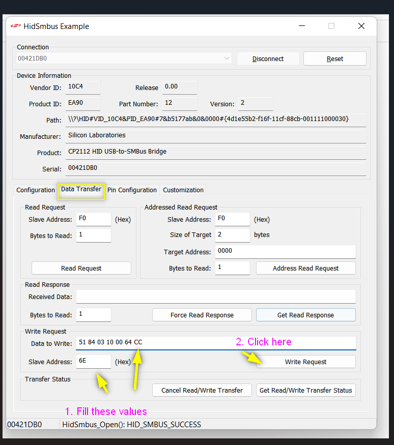
The I2C address of the display is 0x37 (Slave address). But in the application we have to set it to 0x6E. (0x37 « 1 = 6E) left shift 0x37 by one you will get 6E.
Now to set the brightness we have to use the SetVCP commands. First we have to set the below data
data:6E 51 84 03 10
6E Destination address
51 Source address
84 Length
03 Set VCP Feature COMMAND
10 VCP opcode for brightness
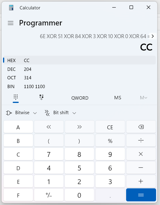
The next two bytes are the brigntess value in hex. e.g for 100% brightness, Convert the 100 into hex which is 0x00 0x64. You can caluclute it using Windows programmer caluclator. 100(DEC) = 0x00 0x64 (Hex).
00 High byte of brightness value
64 Low byte of brightness value
data: 6E 51 84 03 10 00 64
and the last byte is checksum which can be calculate as below
6E XOR 51 XOR 84 XOR 03 XOR 10 XOR 00 XOR 64 = CC
Now the complete data is 51 84 03 10 00 64 CC
Click on write request and send the data, The brightness of display should be change to 100%
Like wise for 10% brightness the data is 51 84 03 10 00 0A A2
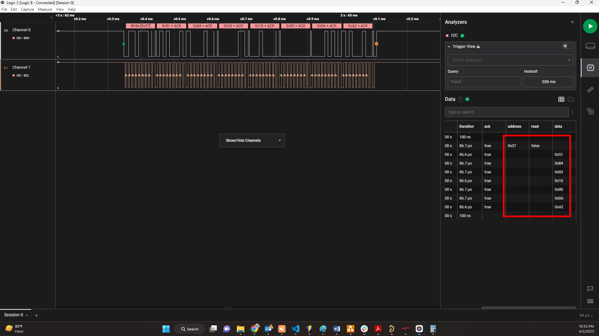
We have connected a logic analyzer to see what actaul data is wrtten on the I2C lines.
Contrast Control
To change the contrast set the VCP opcode to 0x12.
So for 100% contrast the data is 51 84 03 12 00 64 CE
In this way by changing the opcode we can set/control other display settings like tuning ON/OFF display, selecting color preset, changing input mode.
You can find differnt opcodes and detailed infomation of DDC commands below. https://milek7.pl/ddcbacklight/ddcci.pdf https://www.ddcutil.com/getvcp_known_u3011_output/