Introduction
Reverse polarity protection is a must-have in electronic circuits to safeguard devices against accidental damage caused by connecting the power supply in the wrong direction.
Since many products include a power input socket, there is always a chance that users may connect the supply in reverse. Without proper protection, this can lead to permanent circuit damage.
There are multiple ways to implement reverse polarity protection, ranging from simple diode-based solutions to more efficient MOSFET-based designs.
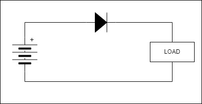
Method 1: Reverse Polarity Protection using Diode
The most basic and inexpensive method is to use a diode in series with the power supply. While this works, it has a major drawback: voltage drop and power loss.
- A standard silicon diode introduces about 0.7V drop.
- A Schottky diode improves efficiency with only 0.3V to 0.4V drop, and can handle higher current loads.
For example, at 3A current:
-
Power loss with Schottky diode:
3A × 0.4V = 1.2W -
Power loss with standard diode:
3A × 0.7V = 2.1W
As current increases, the power loss (and heat dissipation) grows significantly.
This makes diode-based protection unsuitable for low-voltage or high-current applications.
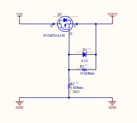
Method 2: Reverse Polarity Protection using P-Channel MOSFET
A more efficient solution is to use a P-Channel MOSFET.
This method has very low voltage drop, supports high current flow, and is generally more reliable.
The circuit uses:
- A P-Channel MOSFET
- A Zener diode
- A pull-down resistor
If the supply voltage is lower than the MOSFET’s Vgs threshold, you can directly connect the gate to ground. For higher supply voltages, the Zener diode ensures the gate-source voltage remains within safe limits.
Working of the MOSFET-Based Circuit
- Correct polarity: The MOSFET turns ON, allowing current to pass with almost negligible resistance.
- Reverse polarity: The MOSFET turns OFF, preventing current flow and protecting the circuit.
For a P-Channel MOSFET, the device turns on only when Vgs is negative (e.g., -2.0V or lower). If the battery is reversed, Vgs becomes positive, and the MOSFET blocks the current.
Power Loss Calculation
Unlike diodes, MOSFETs have an RDS(ON) resistance that determines power loss:
Formula:
Power Loss = I² × RDS(ON)
Example using NVMFS5A140 P-Channel MOSFET with RDS(ON) = 0.0042Ω (max):
- At 1A current:
Power Loss = (1A)² × 0.0042Ω = 0.0042W
This is far less than diode-based losses, making MOSFETs the better choice for efficiency.
Added Protection with Zener Diode
To protect the MOSFET from excessive gate-to-source voltage (Vgs):
- A Zener diode (e.g., 9.1V) clamps the voltage.
- A resistor ensures stable gate drive.
This prevents damage when supply voltages exceed the MOSFET’s Vgs rating.
How to Select the Right MOSFET
When choosing a P-Channel MOSFET for reverse polarity protection, check:
- RDS(ON): Lower values reduce conduction loss.
- Vgs(max): Ensure it won’t be exceeded under reverse polarity conditions.
- Id (Drain Current): Maximum current handling capacity.
- Vdss: Maximum drain-to-source voltage rating.
- Package type: For thermal and PCB layout considerations.
Conclusion
Using a P-Channel MOSFET for reverse polarity protection provides:
- Minimal power loss
- High efficiency
- Better performance in low-voltage, high-current circuits
Although it is slightly costlier than a diode, the efficiency and safety it provides make it the preferred choice for modern electronic designs.
Further Learning
Watch this excellent explanation by GreatScott! for a deeper understanding of the circuit: