How to Customize PCM2704 DAC Name Using EEPROM Programming
The PCM2704 is a popular USB Digital to Analog Converter (DAC) known for its high-quality audio output. By default, it may appear as a generic “USB Audio DAC” on Windows. However, with EEPROM programming, you can customize the device name or add your brand identity. No need to make any Windows device driver.
In this blog, we will guide you through the step-by-step process of changing the PCM2704 DAC name using an EEPROM programmer.
Why Customize the PCM2704 DAC Name?
- Personalize your audio device.
- Easily differentiate between multiple PCM2704 devices.
- Add branding for commercial products.
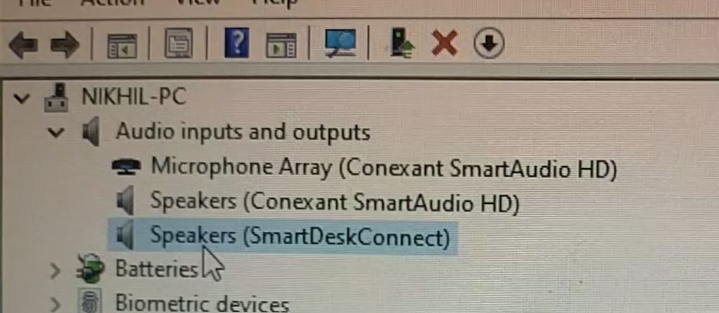
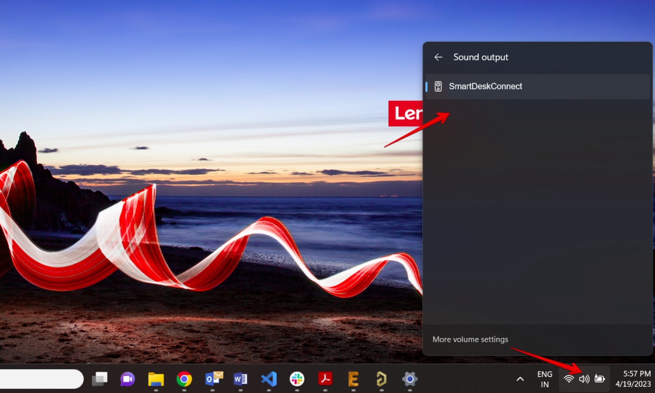
Custome Device name will be shown in Windows sound output.
If you’d like to explore the PCM2704 EEPROM connection, schematic, or PCB details, check out our related blog post. PCM2704 DAC
Understanding the EEPROM in PCM2704
The PCM2704 retrieves its USB descriptors, including the device name, Vendor ID (VID), and Product ID (PID), from an external EEPROM during startup. This data is transmitted via the I2C interface using Pin 3 (DT) for data and Pin 2 (CK) for the clock.
Key Parameters to Note:
- Vendor ID (VID): Identifies the device manufacturer (Default: 0x08BB for Texas Instruments).
- Product ID (PID): Identifies the specific product (Default: 0x2704).
- Device Name: Displayed in Windows as the product name.
- Power and Configuration Attributes.
Preparing Custom Descriptor Data
Lets say we need to change the name to “SMARTDESK CONNECT”, follow these steps to create a hex representation for the EEPROM:
Data Breakdown:
- VID (0x08BB) → Converted to DD 10 (Explained below)
- PID (0x2704) → Converted to 23 E4 (Explained below)
- Product Name: “SMARTDESK CONNECT” using bit-reversed hex values.
- Power Attribute & Max Power: 0x80 for Bus-powered and 0x7D (250mA).
Creation of Hex Data
-
Convert to ASCII: Each character of “SMARTDESK CONNECT” is converted to its corresponding ASCII hex value.
Character ASCII (Hex) S 53 M 4D A 41 R 52 T 54 D 44 E 45 S 53 K 4B Space 20 C 43 O 4F N 4E N 4E E 45 C 43 T 54 -
Reverse Bits: Since PCM2704 reads data in reverse bit order, each byte is bit-reversed.
- Example:
53(01010011) →CA(11001010) - Example:
4D(01001101) →B6(10110110)
- Example:
-
VID and PID Conversion:
- VID 0x08BB → Converted to DD 10
- PID 0x2704 → Converted to 23 E4
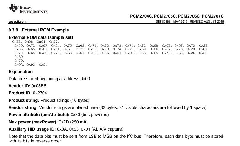
Note: The Texas Instruments datasheet for the PCM2704 contains an error in the VID and PID conversion. Be sure to verify the conversion values.
- Final Hex Data Generation: Combining all values into a complete hex block produces the final EEPROM data as shown above.
Hex Data for SMARTDESK CONNECT
DD 10 23 E4 CA B6 86 4E 2E 22 A6 CE D6 C2 F6 76
76 A6 C6 2E C2 A6 B6 2E 4E A6 1E 34 04 92 76 C6
74 04 04 04 04 04 04 04 04 04 04 04 04 04 04 04
04 04 04 04 03 50 50 C9 80
Writing Data to EEPROM
To write this data to the EEPROM using a universal programmer, follow these steps:
Tools Required:
- EEPROM Part Number: AT24C16A (16Kb Memory). The PCM2704 supports EEPROMs with a memory size of up to 16KB, such as the AT24C16/AT24C08.
- Programmer: MiniPro TL866A Universal Programmer
- Software: MiniPro v6.85
Steps to Write Hex Data:
- Connect the AT24C16A EEPROM to the MiniPro TL866A using the appropriate adapter.
- Open the MiniPro v6.85 software.
- Select the EEPROM part number (AT24C16A).
- Add the hex data into a text file and load it.
- Ensure the starting address is set to 00.
- Click Write to begin programming.
- Perform a Verify to confirm that the data was successfully written.
Refer to this video for detailed programming steps:
Once the programming is complete, solder the EEPROM onto the PCM2704 DAC board. When connected to a Windows PC, it will now display as “SMARTDESK CONNECT”.