Client
SEIDONICS
Product Description
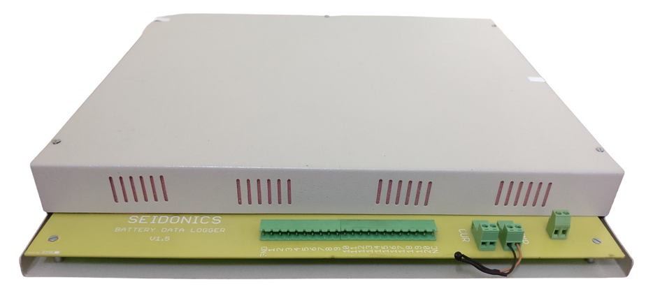
The 20-Channel Voltage Data Logger is designed for battery manufacturing plants to monitor and log voltages of lead acid batteries during the charging and formation process.
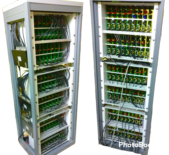
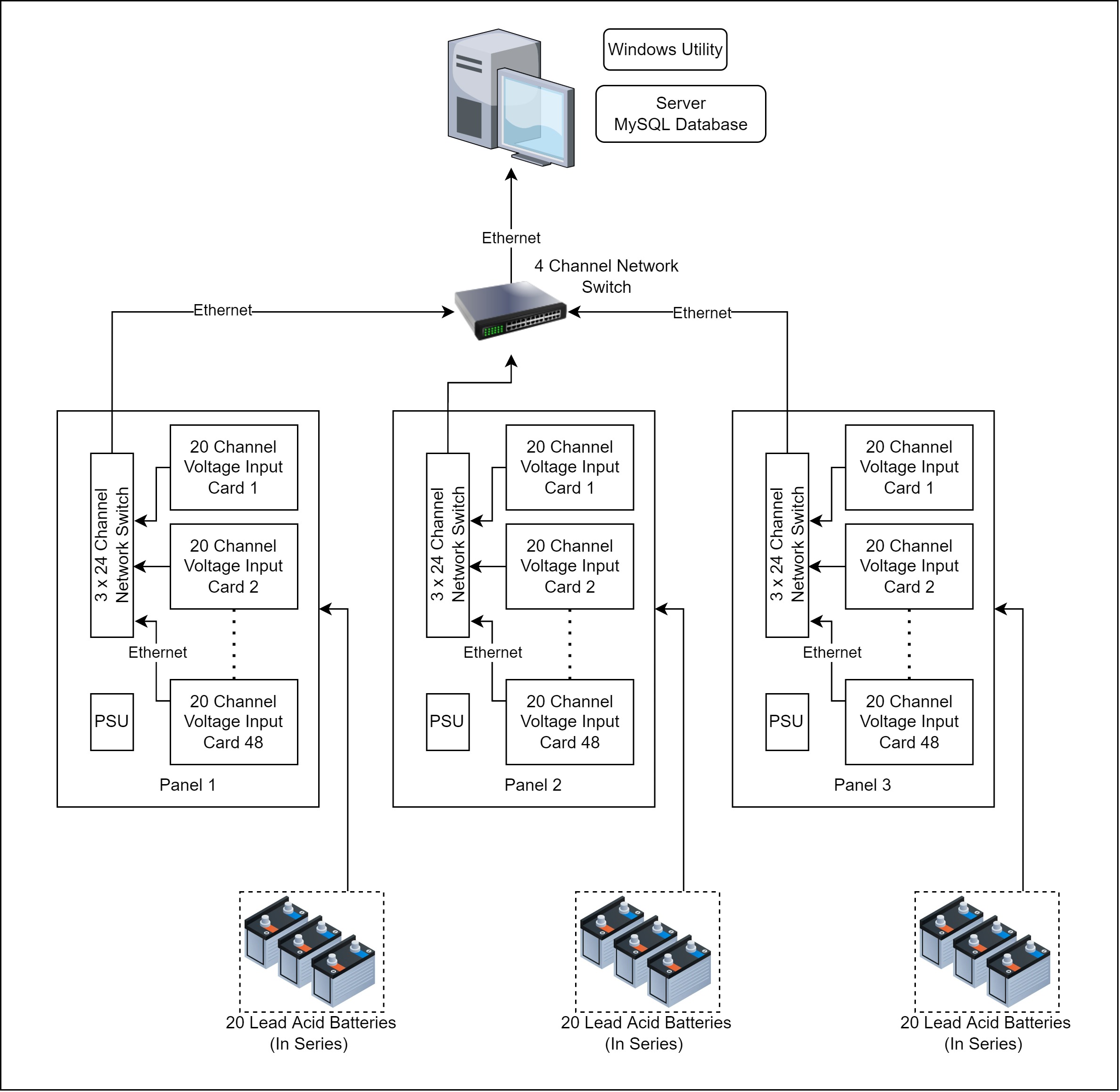
The system is deployed at the EXIDE battery manufacturing facility. The panel is divided into 48 datalogging cards, with each card capable of monitoring 20 batteries connected in series. This allows a single panel to handle 960 batteries.
All recorded data is stored locally on the card and synchronized to a central MySQL database via a Windows server. A 24-port Ethernet switch connects multiple cards to the central system, providing centralized monitoring and data management.
Product Architecture
Working
During the battery manufacturing process, newly assembled lead acid batteries undergo a formation cycle, where they are charged for up to 48 hours using industrial rectifiers. This process is critical to activating the battery plates and ensuring long-term performance.
To maintain quality, the voltage of each battery must be measured at regular intervals to verify that the charging profile is correct. The 20-channel datalogger card plays this role.
Step 1: Trigger-Based Logging
- Each datalogger card has two trigger inputs that are directly connected to the rectifier.
- At predefined intervals, the rectifier sends a trigger signal to the card.
- Upon receiving this signal, the card logs the voltage of all 20 channels simultaneously, capturing an accurate snapshot of battery conditions at that point in time.
Step 2: Data Storage and Transfer
- The logged data is first stored locally on the datalogger card in JSON format.
- A Windows server running a MySQL database collects and manages this data.
- Once the server is online, the card transfers the locally stored logs to the central database by executing automated SQL queries.
- This ensures that even if network connectivity is lost, no data is lost, as the card automatically synchronizes once the server is available.
Step 3: Software Management
-
A custom-designed Windows application is used to:
- Add and configure new cards
- Set trigger intervals
- Create and manage batches of batteries
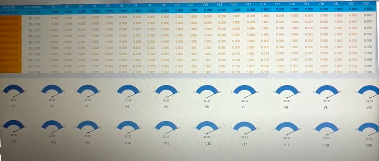
- Display live or stored voltage data
- Generate reports for quality analysis
-
Each card has a unique IP address, allowing the software to identify and manage multiple cards simultaneously.
Step 4: Safety and Fault Detection
- Each channel includes an overvoltage detection feature.
- If a battery’s voltage rises above the set threshold, the card immediately activates a buzzer and turns ON an alert indicator LED.
- This feature helps operators quickly identify faulty batteries or charging issues before damage occurs.
Product Specifications
| Feature | Specification |
|---|---|
| Voltage Measurement Channels | 20 channels |
| Voltage Range | 0V – 20V DC (Max 48V) |
| Measurement Accuracy | ±100 mV |
| Trigger Inputs | 2 digital trigger channels connected to rectifier |
| Communication | TCP/IP over Ethernet |
| Onboard Storage | 4 GB memory per card |
| Input Supply Voltage | 12V DC |
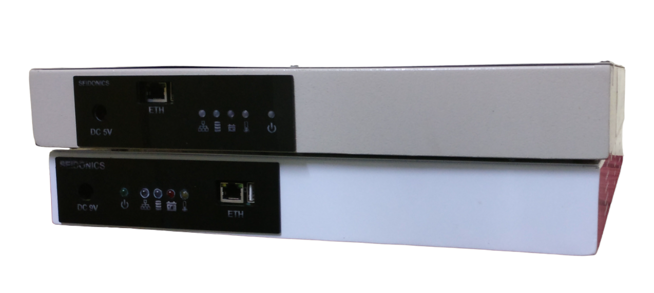
| Indicators | LEDs for Power, Server Live, Logging, Alert |
| Timekeeping | Onboard Real-Time Clock (RTC) |
| Safety Features | Battery overvoltage detection per channel with buzzer & alert indicator |
| Software Support | Interactive Windows software for live display, stored data review, and reporting |
| System Scalability | Single server/software supports up to 7 panels (6,720 batteries in total) |
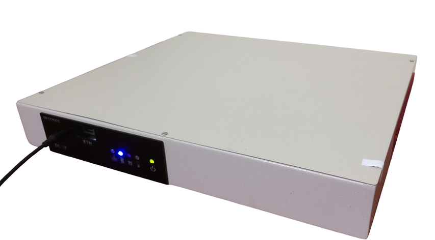
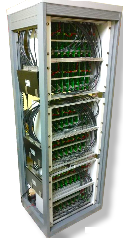
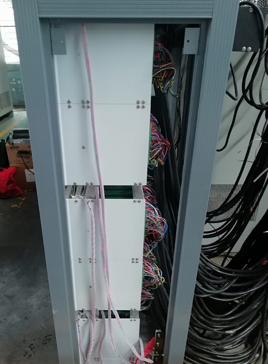
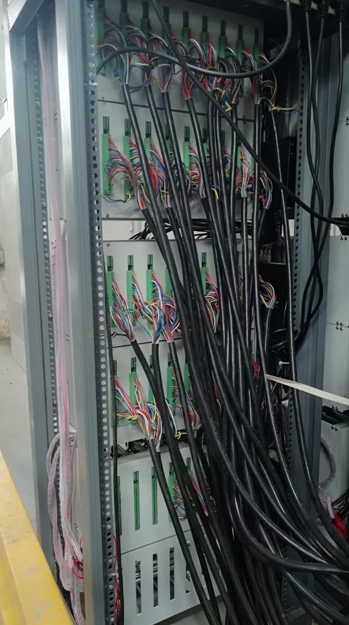
Product Photos/Videos
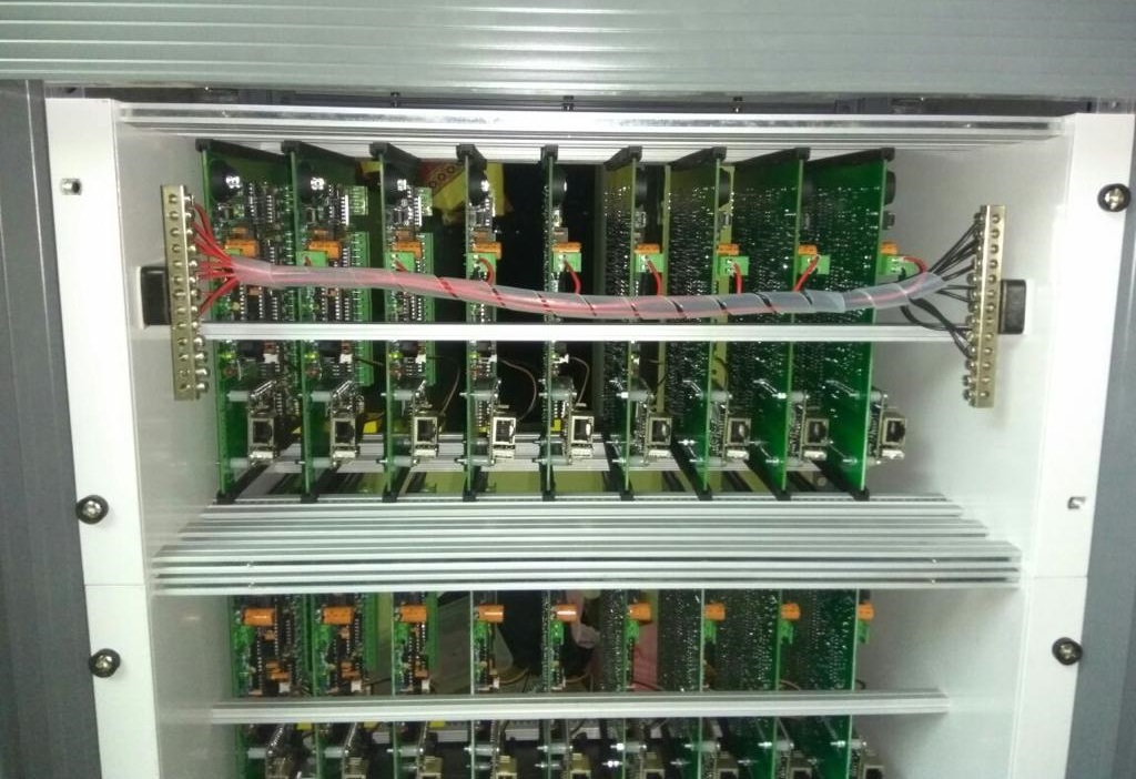
Single Card Version
In addition to the full multi-panel system, the Voltage Data Logger is also available in a single-card configuration. This version is designed for smaller setups, R&D labs, pilot production lines, or standalone testing stations where monitoring fewer batteries is sufficient.