https://en.wikipedia.org/wiki/SAE_J1772
Description
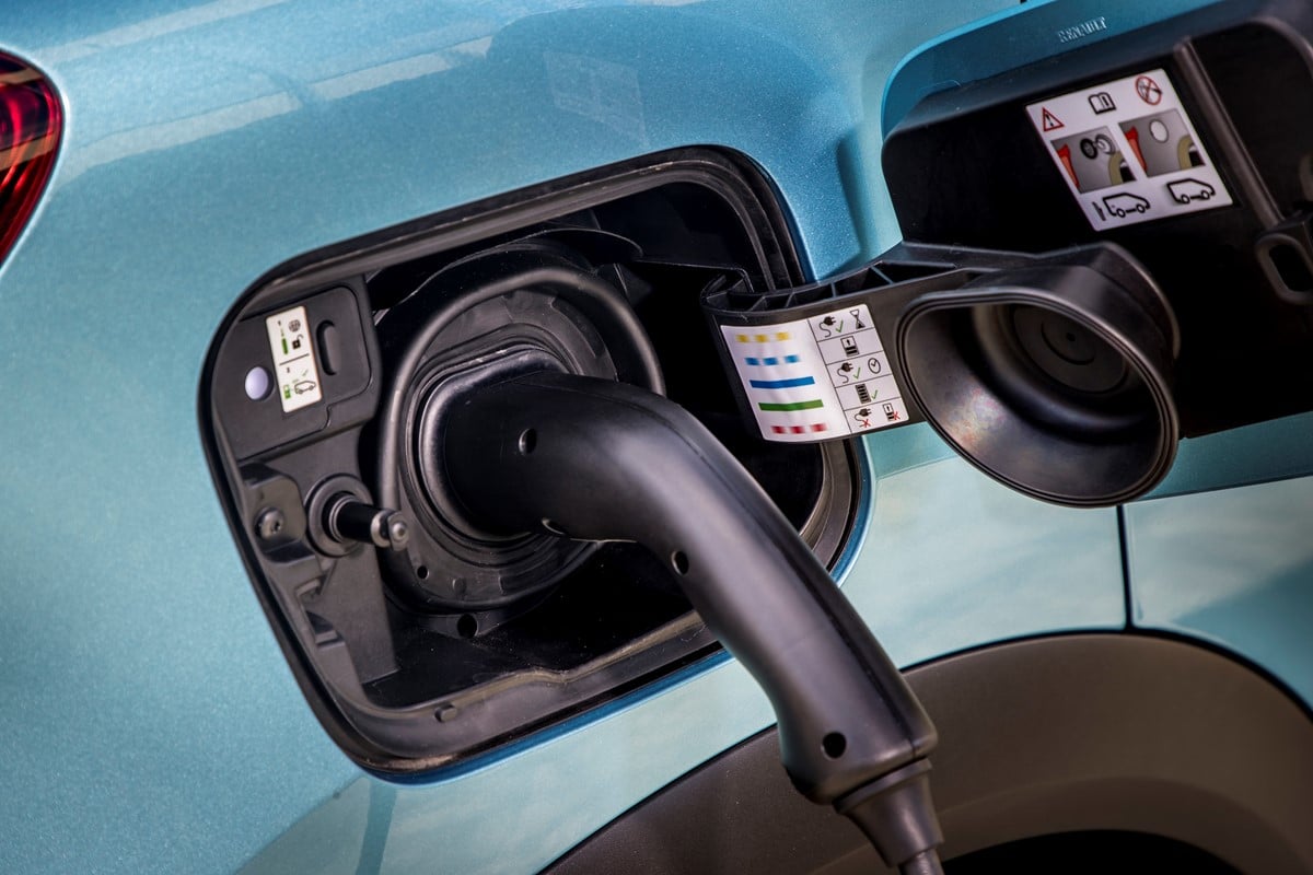
Many Electric Vechical (EV) useS SAE J1772 Type 1 Connector for the charging. The Type 1 connector is connected to a “electric vehicle supply equipment”(EVSE). EVSE supply AC power to the vehicle’s on-board charger, which then converts it to the direct current (DC) needed to recharge the battery.
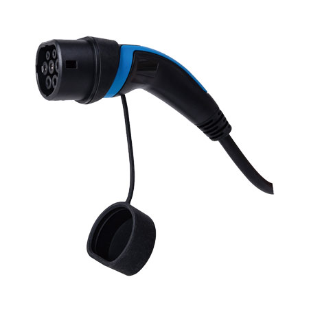
SAE J1772 / IEC 62196-2-1 Type 1 Connector.
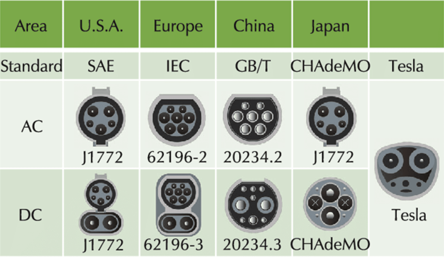
Different types of connector are used in differnet countries. Below is the figure of EV charger connector standars
There are two type of EVSE (Charger)
- AC Charger
- It only supply AC single phase/3 phase power to the vehicle. Rectifier is in the card which convertes the AC into DC and charges the battries.
- DC Charger
- The Charger itself rectifies the AC into DC. DC supply is fed to the vehicle.
There are two EV side connectors, type-1 and type-2.
- Type-1 connector (J1772): It consists of 5 pins. It has charging voltage upto 250V and charging current upto 32 A. Hence AC charging power upto 7 KW can be possible.
- Type-2 connector (62196-2): It supports single phase charging and three phase charging with charging voltage upto 500V and charging current upto 63A. Three phase 400 V charging at 32 A represents charging power of 22 KW.
In this system, AC charger is impliment with IEC 62196-2-1 connector.
The IEC 62196-2-1 has 7 pins.
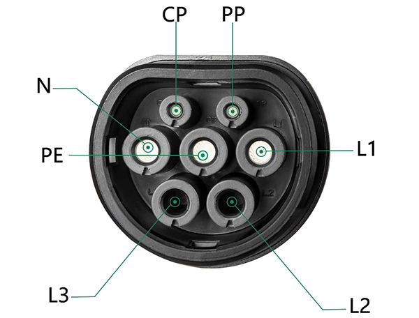
| Position | Signal | Description |
|---|---|---|
| 1 | L1, L2, L3 | AC Phase L1 for Single Phase supply L1, L2, L3 for three Phase supply |
| 2 | N | AC Neutral |
| 3 | PE | Protective Earth / Ground |
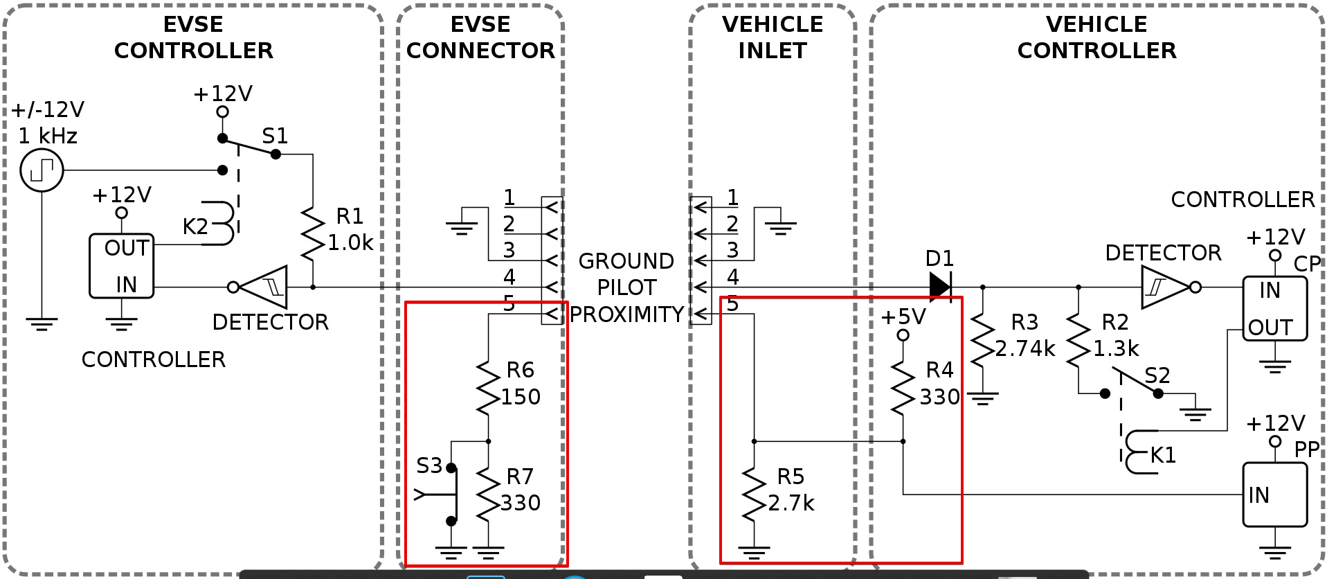
| 4 | PP | “Proximity Pilot”/“plug present”, which provides a signal to the vehicle’s control system so it can prevent movement while connected to the EVSE (Charging station), and signals the latch release button to the vehicle. |
| 5 | CP | “Control Pilot” is a communication line used to signal charging level between the car and the EVSE. 1 KHz square wave at +/-12V is generated by EVSE on the pilot pin to detect the presence of the vehicle, communicate the maximum allowable charging current and control the charging begin/end. |
Working
The signaling protocol has been designed for the negotation with the vehicle. A microcontroller is used in the EVSE to impliment the protocol. The protocl has the diffenr charging states thats need to follow to start the charging. The charging states checks if the vehicle is connected properly, set the charging current, provide the safet feutre. CP pin is used for the communication.
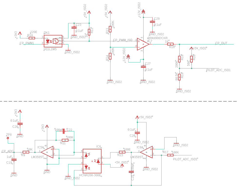
The hardware includes a controller (ESP32), Relay to turn ON/OFF the charger supply, Opamp and other components.
Signaling Circuit
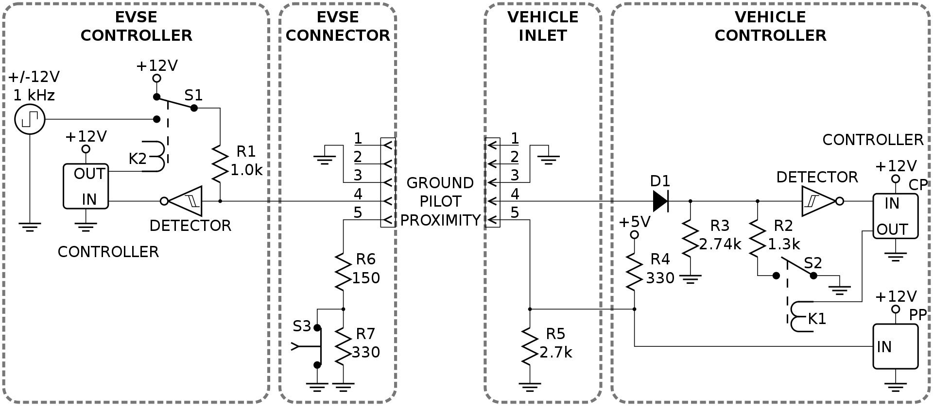
Control Pilot (Mode)
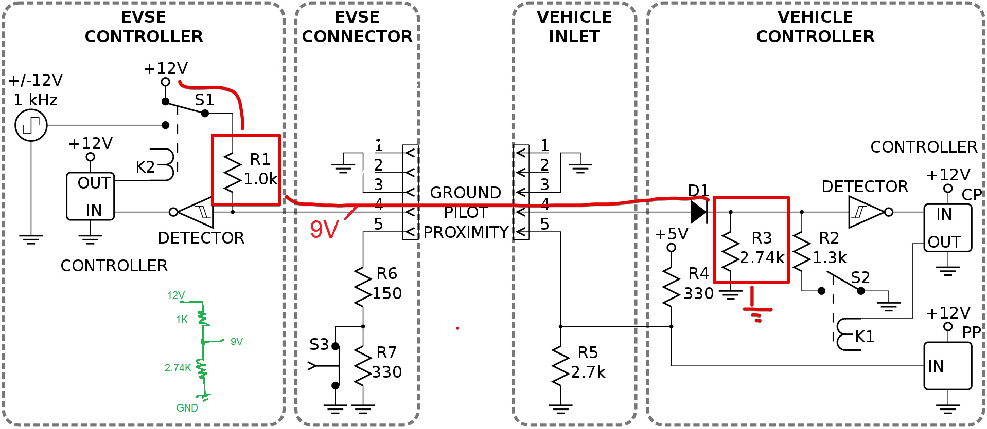
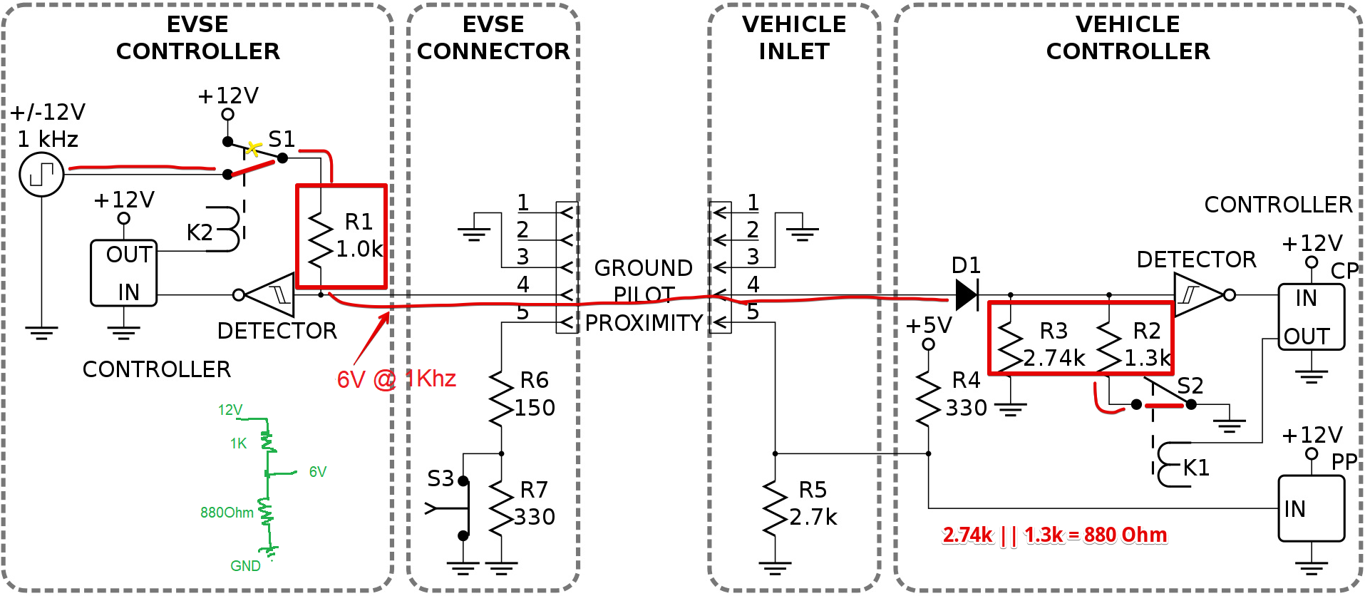
The controller uses a 1 kHz square wave at ±12V on the control pilot that is connected back to the protective earth (GND) on the vehicle side by means of a resistor and a diode (voltage range ±12.0±0.4 V). It forms a voltage divider network. The controller measure the analog voltage present on the CP pin to check the state of the charger(explained below).
Charging Sequence
-
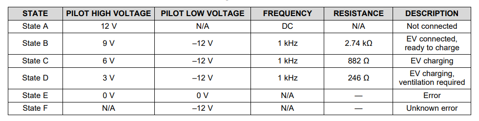
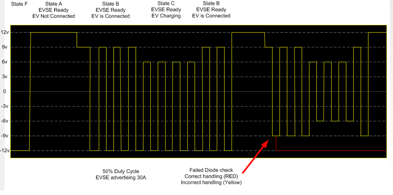
[State A] When the charger is not connected, The controller puts +12V on the control pilot wire. till the votage stays at 12V controllers keep the charger OFF.
-
When the plug has been connected, the vehicle places a 2.74kΩ load on the pilot line, It forms a voltage divder circuit (1kΩ in the EVSE and 2.74kΩ in the vehicle) which drops the voltage to 9 V. It indicate that EV is ready for charging.
-
[State B] When the voltage is set to 9V, Controller enables the PWM, which signals the vehicle how much current it can draw. The EVSE also closes the relays, providing power to the vehicle.
-
[State C] The vehicle starts to draw power and switches to the 822Ω load, which drops the voltage to 6 V, signaling the EVSE that charging has started.
-
Most vehicles continue to pull low amounts of power in state C, even when fully charged, so the charging process is ended by unplugging the cable, which returns the voltage to 12 V. The controller measures this process and closes the relays and returns to State A.
The diode preset in the vehicle will only make for a voltage drop in the positive range; any negative voltage on the CP-PE loop is blocked by D1 in the vehicle. It a safety function. Like if the connector drops in the water or any short circuit happens on the pin then negative voltage also transfers on the CP pin. So if that happens the controller turn OFF the power.
Control Pilot (Current Control)
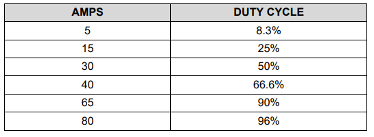
The duty cycle of the pilot signals communicates the limit of current the EVSE is capable of supplying to the vehicle; the vehicle can then use up to that amount of current for its charging circuitry. This current rating is primarily determined by the electromechanical components in the EVSE, such as conductors, relays, contactors, and the service connection.
The controller uses the PWM to set the 1Khz wave duty cycle as per the current provided by charger.
Example
Example of CP line communication
Proximity Pilot (PP)
PP pins uses to turn off the power in case of the charger removal. If the connector removed directly when the chrging is going on, it can create a spark due to high current flowing through the connector. It also uses to indicate the cable current carring capacity.
The proximity pin (PP) is connected to the switch (S3). Switch is mechanically linked to the connector latch release actuator. During charging, the EVSE side connects the PP-PE loop via S3 and a 150 Ω R6; when opening the release actuator a 330 Ω R7 is added in the PP-PE loop on the EVSE side which gives a voltage shift on the line to allow the electric vehicle to initiate a controlled shut off prior to actual disconnection of the charge power pins.
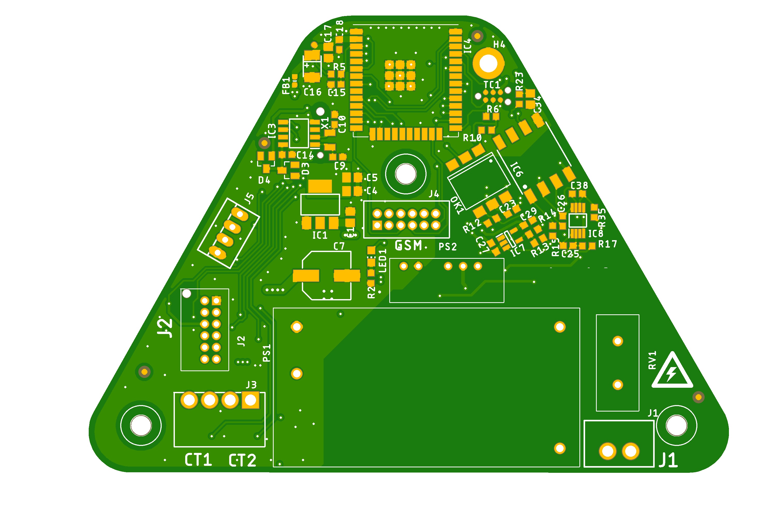
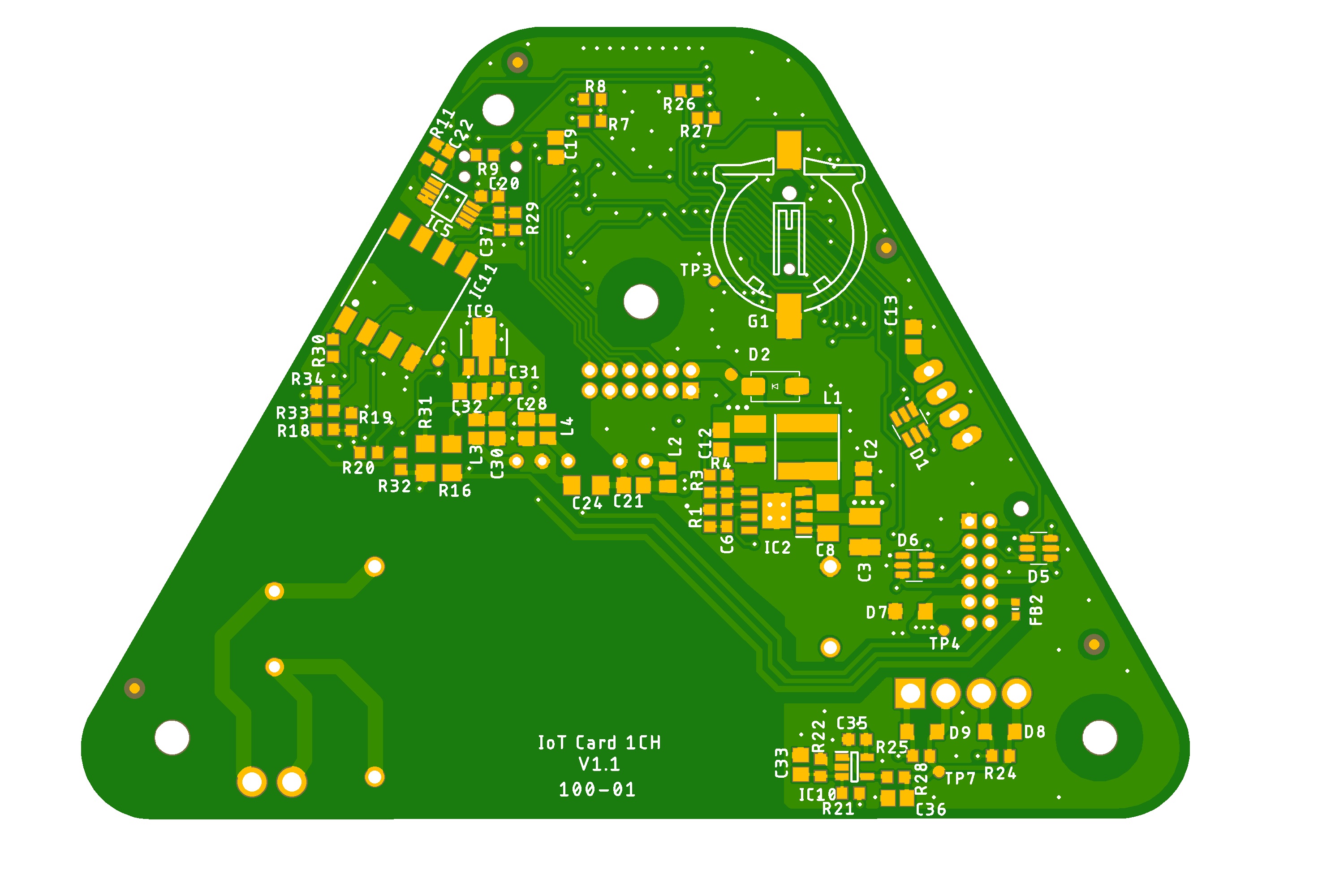
EVSE Product Hardware
CP block schematic used in Product
EVSE Product PCB Photo