In hazardous environments such as oil refineries, chemical plants, and mining operations, electrical devices must be designed to prevent sparks, excessive heat, or electrical discharge that could ignite flammable gases, vapors, or dust. Intrinsic safety (IS) is a design approach that ensures electronic circuits operate at energy levels too low to cause ignition.
To meet intrinsic safety certification requirements, a product was designed for use in petrochemical environments while adhering to industry safety standards. The following steps were followed to ensure compliance and secure certification.
1. Understanding Intrinsic Safety Requirements
Before starting the design process, the relevant intrinsic safety standards were reviewed and implemented:
- IEC 60079-11 (International Standard)
- ATEX Directive (2014/34/EU) (Europe)
- UL 913 (United States)
- IECEx Scheme (Global Certification)
These standards define voltage, current, capacitance, and inductance limits based on the hazardous zone classification.
Hazardous Area Classification and Safety Levels
The product was designed for operation in hazardous environments and classified accordingly:
- Zone 0: Explosive atmospheres are present continuously. Requires Ex ia protection. Example: Inside fuel storage tanks.
- Zone 1: Explosive atmospheres occur during normal operation. Requires Ex ib protection. Example: Chemical processing areas.
- Zone 2: Explosive atmospheres are present only occasionally. Requires Ex ic protection. Example: Ventilation zones near hazardous areas.
Product Design & Division
To meet the intrinsic safety requirements for different hazardous zones, the product was divided into two separate parts:
-
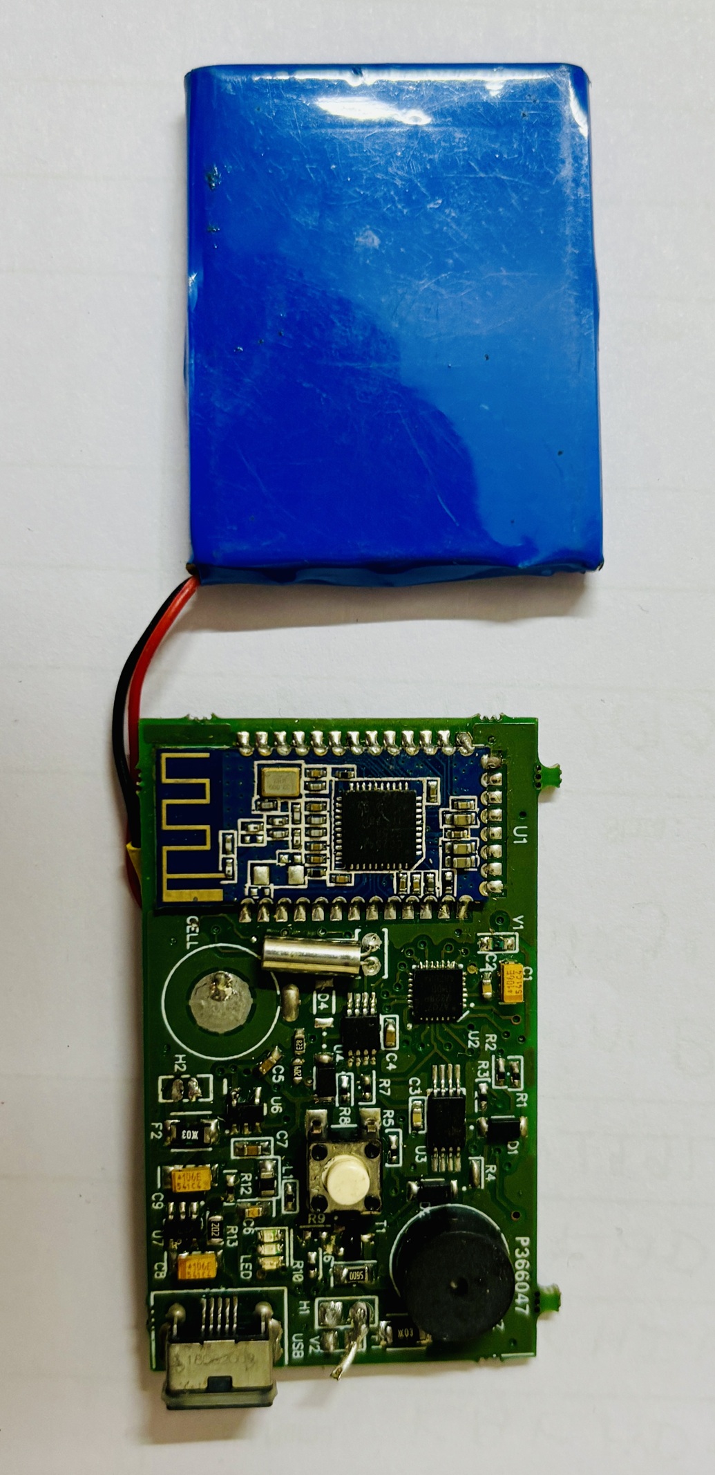
Battery-Powered Unit with Bluetooth
- This part is designed to comply with Zone 1 standards.
- It incorporates a low-energy wireless communication module to transmit data without physical connections.
- Since battery storage is a potential ignition source, strict current and voltage limitations were implemented to ensure compliance.
-
Non-Battery Unit
- This part is designed to comply with Zone 0 standards.
- It does not contain any energy storage components, making it suitable for environments where explosive atmospheres are present continuously.
- The unit is powered by exrenaly by the first unit, ensuring safety in the most hazardous conditions.
For more information about the product, check this link: [Insert Product Link Here]
2. Designing an Intrinsically Safe PCB
To comply with intrinsic safety requirements, the schematic and PCB layout were developed while following strict design guidelines:
1. Energy Limitation
- Voltage Limitation: Maintained below 30V DC.
- Current Limitation: Restricted to under 100mA to prevent sparking.
- Power Dissipation: Controlled to avoid excessive heating.
2. Protection Components
- Zener Diodes: Used for voltage clamping to prevent overvoltage conditions.
- Current-Limiting Resistors: Ensured that excessive current draw was prevented.
- Fuses & PTCs: Prevented overcurrent and power dissipation failures.
3. Component Selection and Placement
-
Use of Certified Components:
- Components selected were certified for intrinsic safety and capable of operating in extreme conditions without compromising safety. Like ATEX certified GSM module (Ublox).
- The components were reviewed to ensure they operated within specified temperature ranges to avoid self-ignition risks.
-
Minimize Energy Storage:
- Capacitance and inductance values were minimized to reduce stored energy that could cause sparking.
- If necessary, these components were protected using current-limiting resistors and Zener diodes to ensure compliance with IEC 60079-11 energy limits.
4. Circuit Design Strategies
-
Redundancy and Fault Tolerance:
- Dual Zener diodes were added as redundant voltage clamps to prevent overvoltage in case of failure.
- Fail-safe mechanisms were integrated to ensure that no single component failure could lead to excessive energy release.
-
Current and Voltage Limitation:
- Series resistors were strategically placed to limit current and prevent excessive power flow.
- Voltage clamping devices were used to ensure overvoltage protection and keep all circuit elements within safe operational levels.
5. PCB Layout Rules
-
Creepage & Clearance Distances:
- Designed per IEC 60079-11 standards to prevent arcing and ensure safe operation in hazardous environments.
-
Isolation Techniques:
- Used galvanic isolation and optocouplers for safe signal transmission and to prevent high-energy transfers across circuits.
-
Conformal Coating:
- Provided protection against environmental contamination, such as dust, moisture, and chemicals, ensuring long-term safety compliance.
-
Thermal Management:
- The PCB layout was optimized for heat dissipation to prevent component temperatures from reaching ignition levels.
- Heat sinks and thermal vias were used to improve heat management and enhance reliability.
6. Testing and Validation
-
Comprehensive Testing:
- The design was tested under normal and fault conditions to ensure compliance with intrinsic safety standards.
- Thermal analysis, spark ignition testing, and electrical failure simulations were conducted to validate safety mechanisms.
-
Regular Inspections:
- The design incorporated mechanisms for regular inspection and maintenance to ensure ongoing safety compliance.
PCB
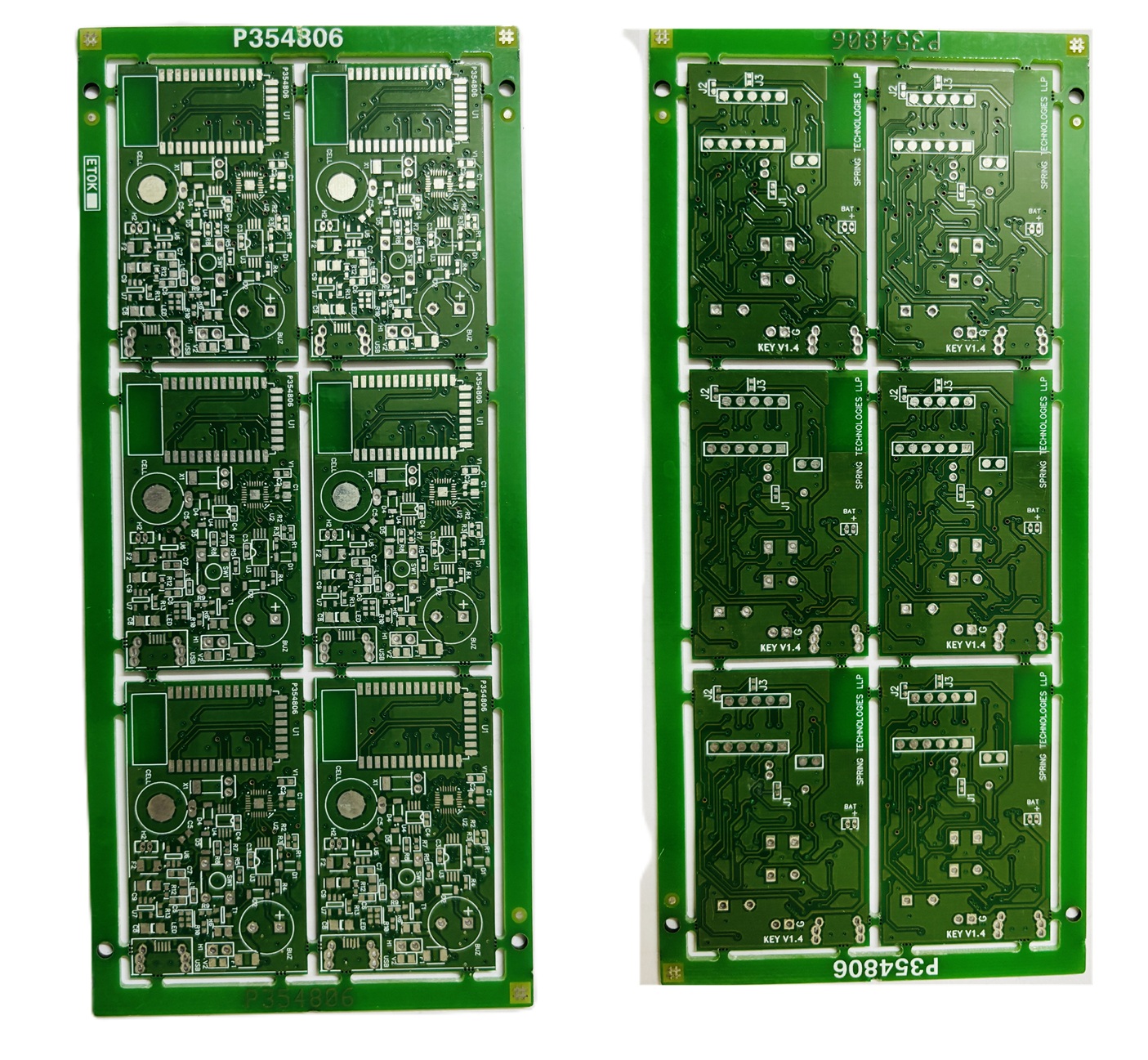
- KEY PCB
- KEY PCB
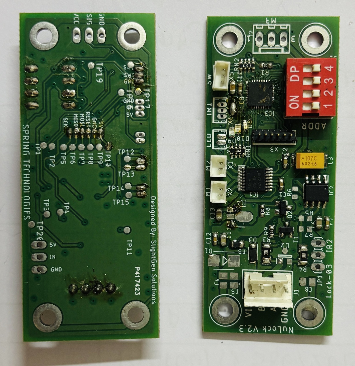
- LOCK PCBA
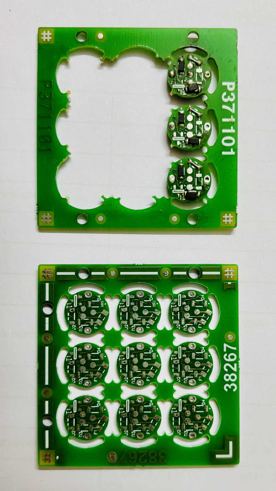
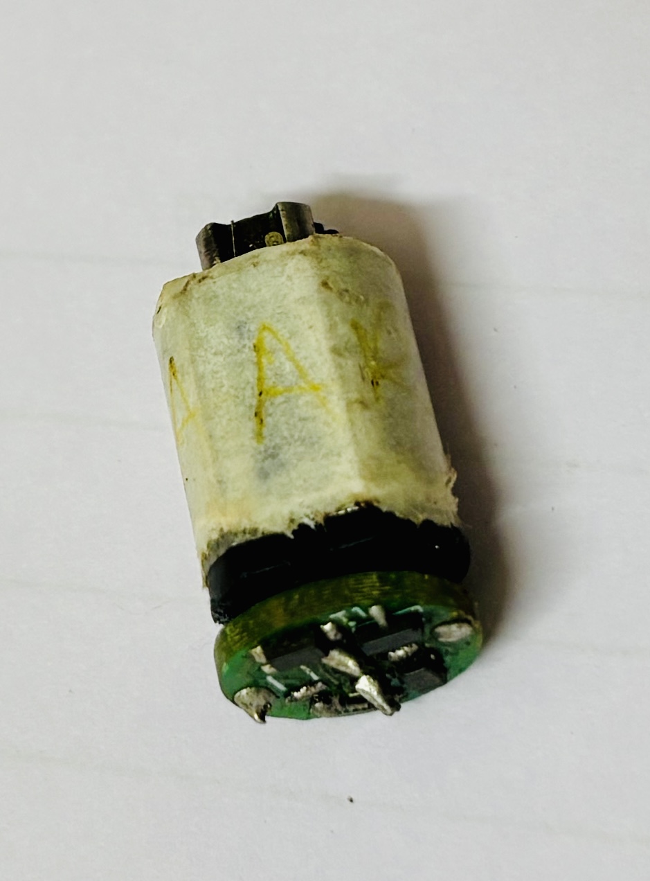
- MOTOR USED IN INTRNSIC SAFE DEVICE
3. Certification Process in India
For electronic devices used in hazardous areas in India, compliance with PESO (Petroleum and Explosives Safety Organization) is required. The following steps were followed to secure certification:
Step 1: Design Review
- The PCB and schematic were evaluated for compliance with IS/IEC 60079-11 standards.
- Documentation, including design calculations, component selection, and safety reports, was prepared.
Step 2: Prototype Testing
- A prototype was developed and subjected to fault condition testing, ensuring it adhered to intrinsic safety requirements.
- Thermal analysis, spark ignition testing, and electrical failure simulations were conducted.
Step 3: Certification Testing at an Approved Lab
- The product was sent for official testing and validation in Nagpur, where certified labs conducted compliance assessments.
Step 4: Documentation and Submission
- A technical dossier was compiled, including test reports, design justifications, and compliance evidence.
- The application was submitted to PESO for certification approval.
After meeting all requirements, the certification was granted, allowing the product to be safely deployed in petrochemical environments.